11. Installation Notes
11.1. Electrical Power Connection
Keep the autopilot OFF when making electrical connections. Turn the autopilot off by turning the RUDDER control counterclockwise to the OFF position. Turn the autopilot ON by turning the RUDDER control clockwise from the OFF position past 1. Do not use a circuit-breaker or external switch to power the unit ON or OFF: keep the RUDDER control in the OFF position when not using the autopilot.
Connect the autopilot power cable to a good 12-volt power source. The red wire connects to +12V.
Use a good quality 10-amp circuit breaker or use the included 10-amp inline fuse-holder. Do not install the fuse-holder in a place exposed to the weather: it is not waterproof.
If possible, use a circuit breaker or switch for better separation from the boat’s electrical system when not in use.
Do not tie into the ignition side of any source.
Use the shortest wire run possible and make good, solid connections.
Apply dielectric grease to all connections to prevent oxidation.
A waterproof connector may be used on the power line, however, do not use a push-in or cigarette-lighter type connector. Use a connector with a screw-down cap and plug, and a compression fitting those seals the cable-jacket as it enters the connector housing. Tin the wire ends. Always keep the cable jacket sealed; an open or damaged jacket can allow water into in the autopilot and connector. Apply dielectric grease to the wire ends and connector pins/sockets to prevent corrosion.
11.2. Power Cable Extensions
If necessary, the power cable can be extended using the appropriate wire gauge for the length of the extension:
12 AWG (4 mm²) extension wire, up to 10 feet (3 m). Total length from motor box: 20 feet (6 m).
10 AWG (6 mm²) extension wire, up to 15 feet (4.5 m). Total length from motor box: 25 feet (7.6 m).
8 AWG (10 mm²) extension wire, up to 20 feet (6 m). Total length from motor box: 30 feet (9 m).
Warning
Using a wire gauge that is too small will cause voltage drop and increased motor wear.
11.3. Control Box Mounting Requirements
The control box MUST be mounted away from anything magnetic that may influence it.
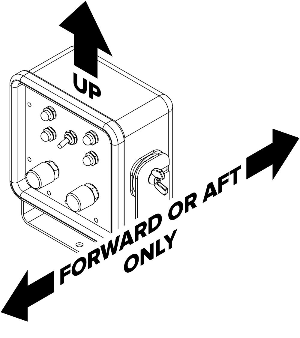
The control box must be oriented level and facing either the bow or the stern of the boat. The cable exits the bottom side of the box. If the control box does not face the bow or stern of the boat, the autopilot heading will be affected by the boat pitching and heeling.
The location should be checked with a handheld compass. See “How to check for magnetic interference” on page 23.
Only use included 316 stainless fasteners for mounting the control box. Other fasteners and grades of stainless steel may be magnetic or become magnetized.
Do not cut or splice the control box cable. If routing is preferred, complete sea trials BEFORE routing the cable to ensure the mounting location is free of magnetic interference.

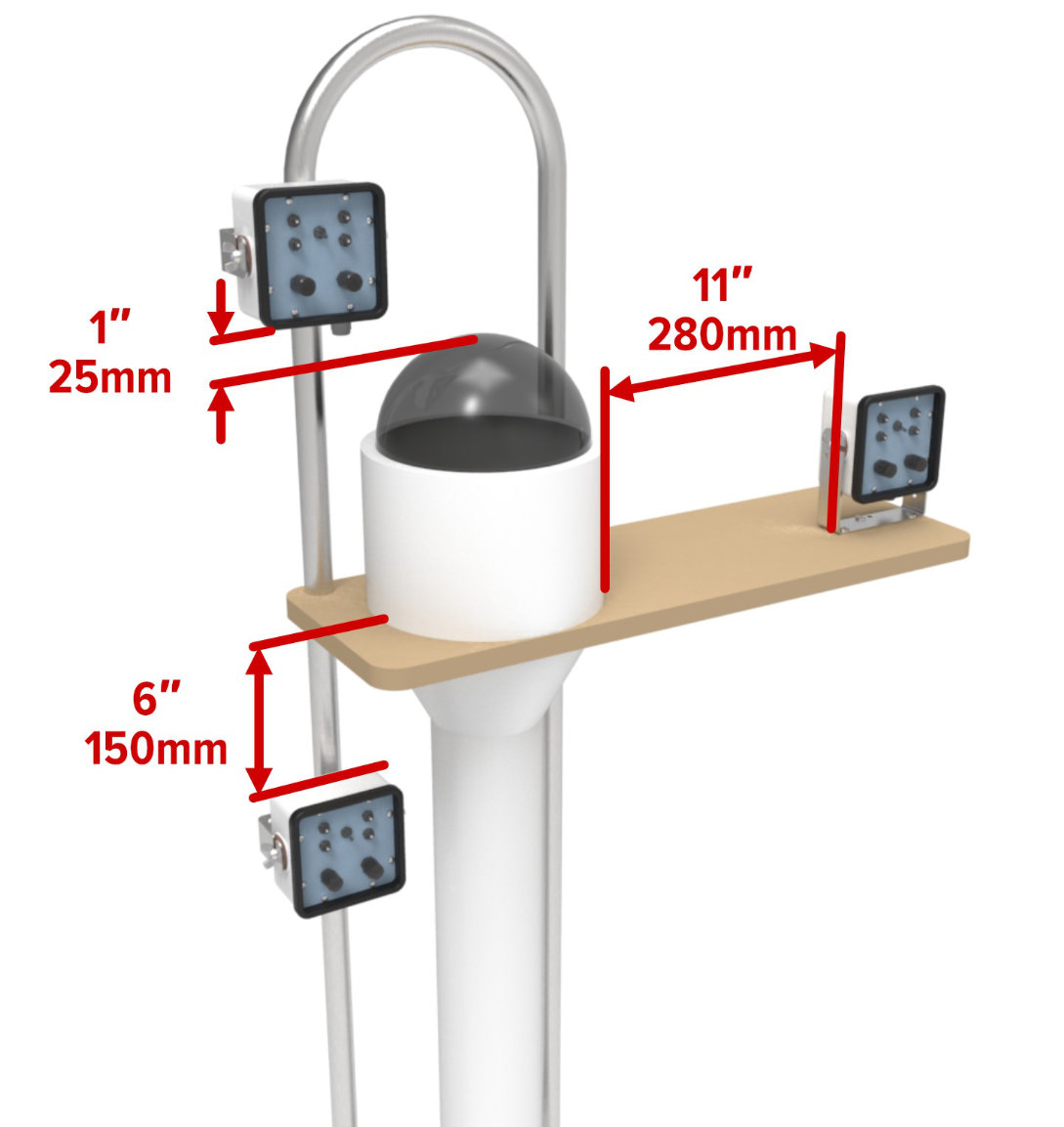
Recommended Control Box Mounting Clearances
As measured on a typical helm—the magnetic environment of your helm may vary. At these distances there was less than 5° compass needle deflection; closer distances caused a 5° or higher needle deflection.
Control Box Guardrail Mounting
The top of the control box should be at least 6” (150mm) under the ship’s compass casing.
The bottom of the control box should be at least 1” (25mm) above the ship’s compass bubble.
Control Box mounting on ship’s compass shelf
At least 11” from the side of the ship’s compass.
Stereo Speakers
The magnetic field from stereo speakers can extend 20” – 30” (500mm – 750mm) from the center of the speaker outward in a donut shape.
Autopilot Motor Box
Mount the control box a minimum 18 inches (450 mm) away from the motor box
Only use included 316 stainless fasteners for mounting the control box. Other fasteners and grades of stainless steel may be magnetic or become magnetized.
Warning
Possible sources of magnetism include:
The autopilot motor
304/18-8 stainless steel screws (they can become magnetized)
Ship’s compass housing (contains declination compensation magnets)
Current carrying wires including solar panels and related cables
Chart plotters and nav screens (check “compass-safe” distance in manual)
VHF Radio and handheld microphone
