8. Maintenance and Adjustments
8.1. General Maintenance and Storage
After use, rinse salt off; lightly spray with fresh water and lightly wipe the CPT down with a cloth and dry it. Do not use alcohol or solvents to clean the motor box or control box as they may remove the paint and graphics. Store the unit in a dry place when not in use or protect it with a wheel/binnacle cover or other appropriate cover. When the boat is laid up, take the pilot home if possible. Each season apply a light coat of marine or automotive wax to the boxes to maintain the powder coated finish.
Warning
Do not store the autopilot in a damp locker, or a location subject to flooding or damp conditions.
Store control box and motor boxes on their sides, with the controls and clutch facing sideways, not facing up/down.
Do not store the control box near anything magnetic—store 18” away from the autopilot motor.
8.3. Belt Tension
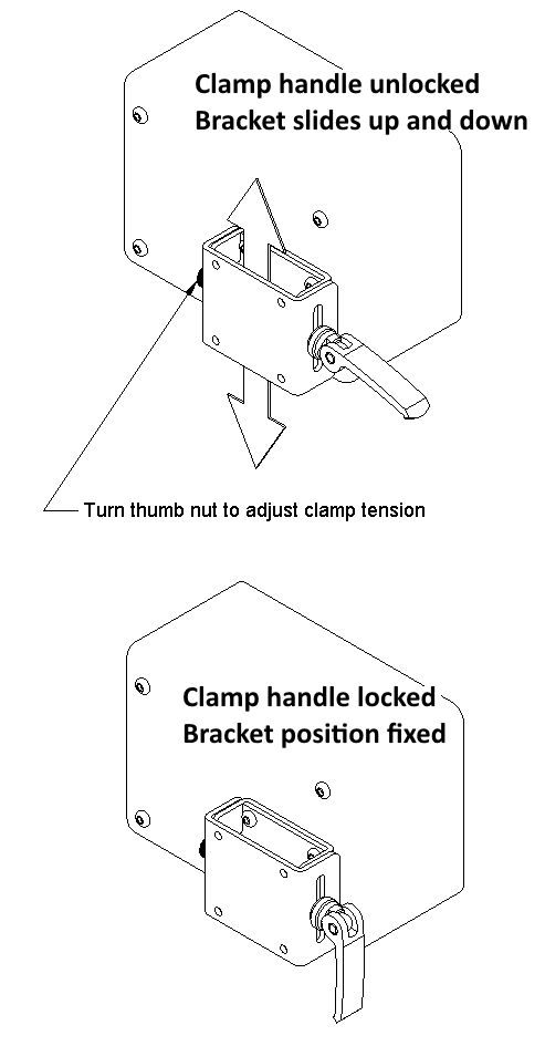
Unlock the clamp lever and slide the motor unit down on its mounting bracket slots with your hands to tension the belt. Pull the belt snug by putting downward pressure on the motor box with your hand and then locking the clamp lever. The clamp lever tightness can be adjusted by unlocking the lever and tightening or loosening the knurled thumb nut.
Do not over-tension the belt. Excessive tension causes clutch wear, makes the clutch difficult to operate and may damage the motor shaft. Over-tensioning also removes any beneficial “give” in the drive system. If it does not slip it is tight enough. An over-tightened belt will not allow any give; a less tensioned belt will give warning of heavy loads or striking the rudder-stops with a skip and thump.
NOTES FOR PEDESTAL MOUNTED INSTALLATIONS
The hose-clamps on the pedestal bracket may need to be re-tightened after the foam padding compresses.
The pedestal bracket may need to be fastened directly to the pedestal with screws if the hose-clamps slip under heavier loads. This is especially the case with Reverse Vertical Pedestal Mounts due to the extra leverage.
8.4. Drive Pulley and Clutch Maintenance
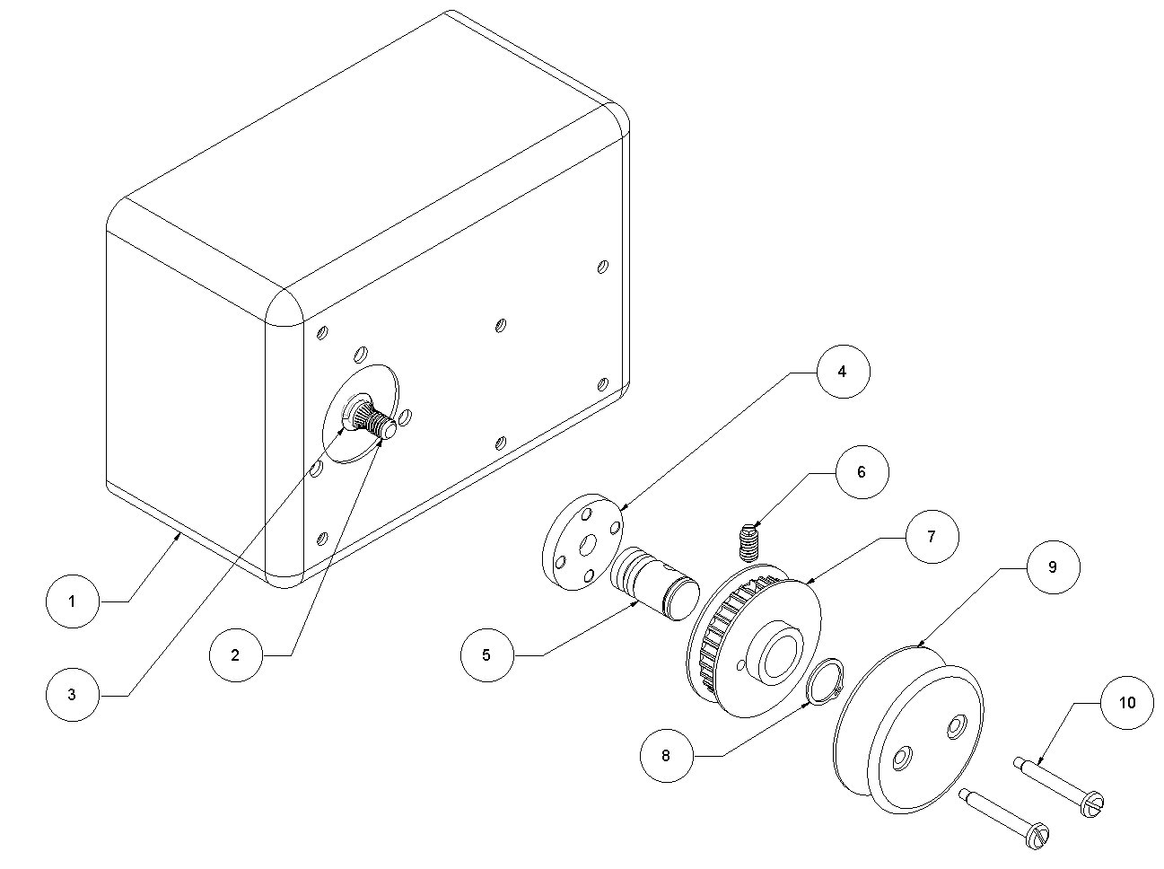
Clutch Assembly Diagram
Item # |
Part Name |
Part # |
|---|---|---|
1 |
Motor Box |
|
2 |
Motor Shaft |
|
3 |
Motor Shaft O-Ring, size 110 |
37-0004 |
4 |
Drive Plate |
53-0009 |
5 |
Drive Shaft 5⁄8” or 1⁄2” |
53-0012 |
6 |
Ball Spring Detent |
98-0039 |
7 |
Drive Pulley Gear |
53-0007 |
8 |
Retaining Ring 5⁄8” or 1⁄2” |
42-0013 |
9 |
Pulley Cap |
98-0027 |
10 |
Shear Pin #10-32 |
98-0030 |
General Drive Pulley and Clutch Maintenance
The drive pulley is held in one of two positions (engaged or disengaged) on its shaft by a detent (spring-loaded ball), which fits into one of two grooves on the shaft. All parts are made of Delrin, Nylon or stainless steel.
Most clutch wear is caused when hand-steering under high belt tension without lubrication. Lubricate the drive pulley and shaft periodically. Salt water may leave salt crystal build-up in the detent. The drive pulley should be periodically removed from the drive plate and cleaned and greased—more often in severe or heavy use conditions. If the autopilot will not be steering for a while, remove the belt from the drive pulley and hang it over the binnacle or wheel shaft. This will lessen wear and prolong the life of the clutch when hand steering.
Important
Each season service and lubricate the clutch. You should not remove the drive plate unless the broken head of a shear-pin is stuck behind the drive plate.
Loosen tension on the drive belt and remove belt from the drive pulley.
Remove the two screws from the back of pulley cap; these are the shear pins. (The black disc used to engage and disengage the clutch is the pulley cap.) Do not attempt to remove the shear pins if the pin ends are bent. Reach and straighten them first using long-nosed pliers.
Remove pulley cap.
Remove stainless steel retaining ring from its groove at the end of the shaft.
Remove drive pulley.
Rinse drive pulley in fresh water. Work the ball inside the shaft-hole in and out.
Clean, dry, and lubricate shaft. Work lubrication into the ball inside the shaft-hole.
Replace drive pulley, retaining ring, and pulley cap.
Replace the two shear pins. Do not over-tighten: threads can strip or the drive pulley may distort causing stiff operation. Rotate the pulley on the shaft and observe the ends of the shear pins.
Shear Pin Clearance Adjustment
There should be an even gap of about 1⁄16” (5mm) between the end of the shear pins and stainless steel drive plate. If one of the pins is too close to shaft-plate, it may tend to catch in the plate holes when the wheel is turned. If the pulley does not turn freely, the pins are not even, or the pins are too close to the shaft-plate: back off one or both screws slightly.
Detent Adjustment
If the clutch does not stay engaged the detent may need adjustment. Never overtighten the detent—the detent housing can mar the drive shaft if screwed all the way in. There is a slotted set-screw in the gear teeth to adjust the ball spring detent.
Carefully tighten or loosen the detent screw about 1⁄8 turn.
Test the operation of the clutch.
The clutch gear should stay engaged. If the detent is too loose, the clutch may inadvertently disengage
When disengaged clutch gear should spin freely without friction on the detent ball
Drive Plate Removal Instructions
The Drive Plate does not need to be removed as part of normal maintenance. It may need to be removed if a broken shear pin head becomes trapped behind it. (If you hear a screeching or scraping sound, this may be the cause.)
Make sure the ends of the two shear pins are not bent, then remove them from the back of the clutch by unscrewing.
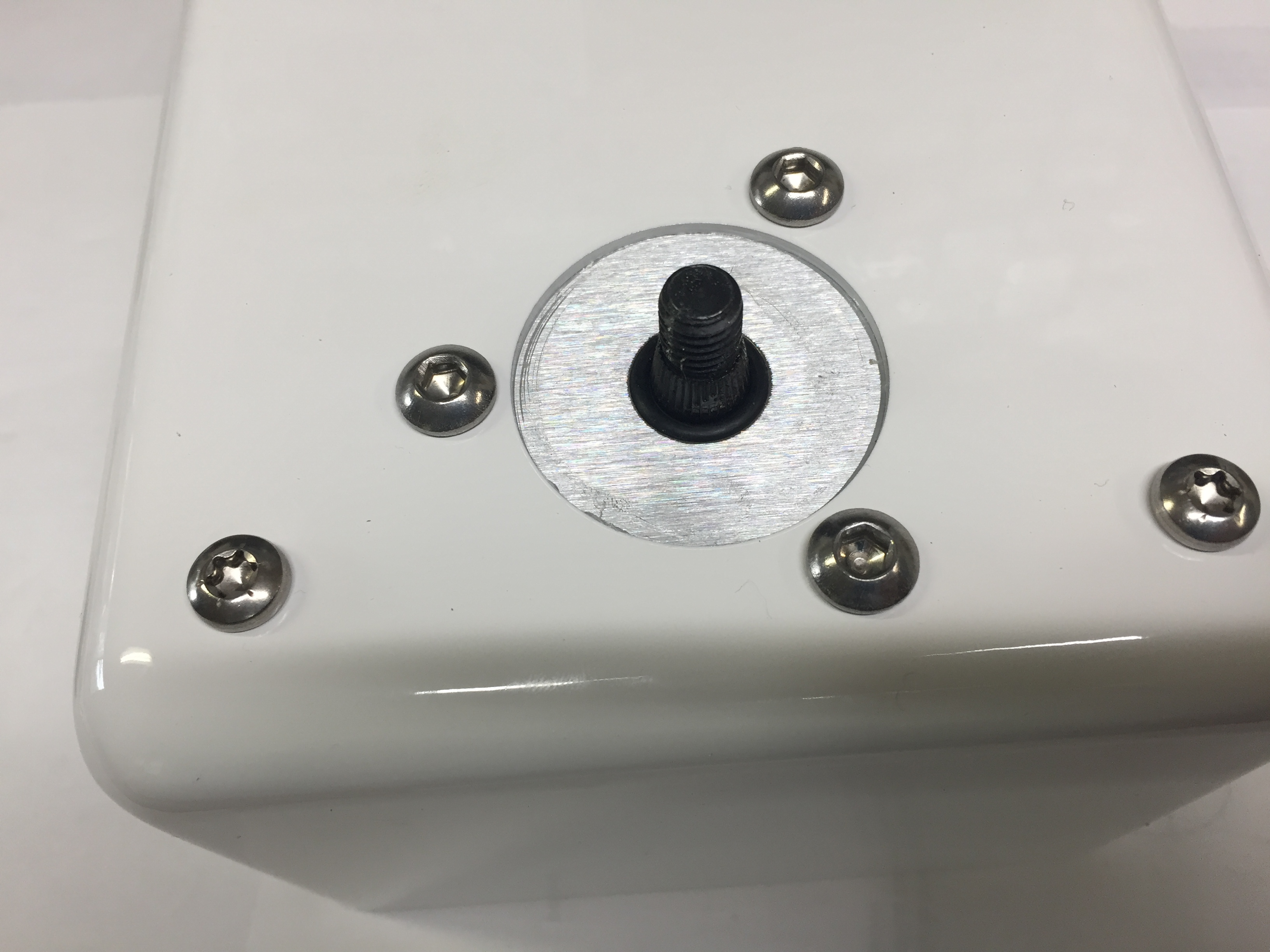
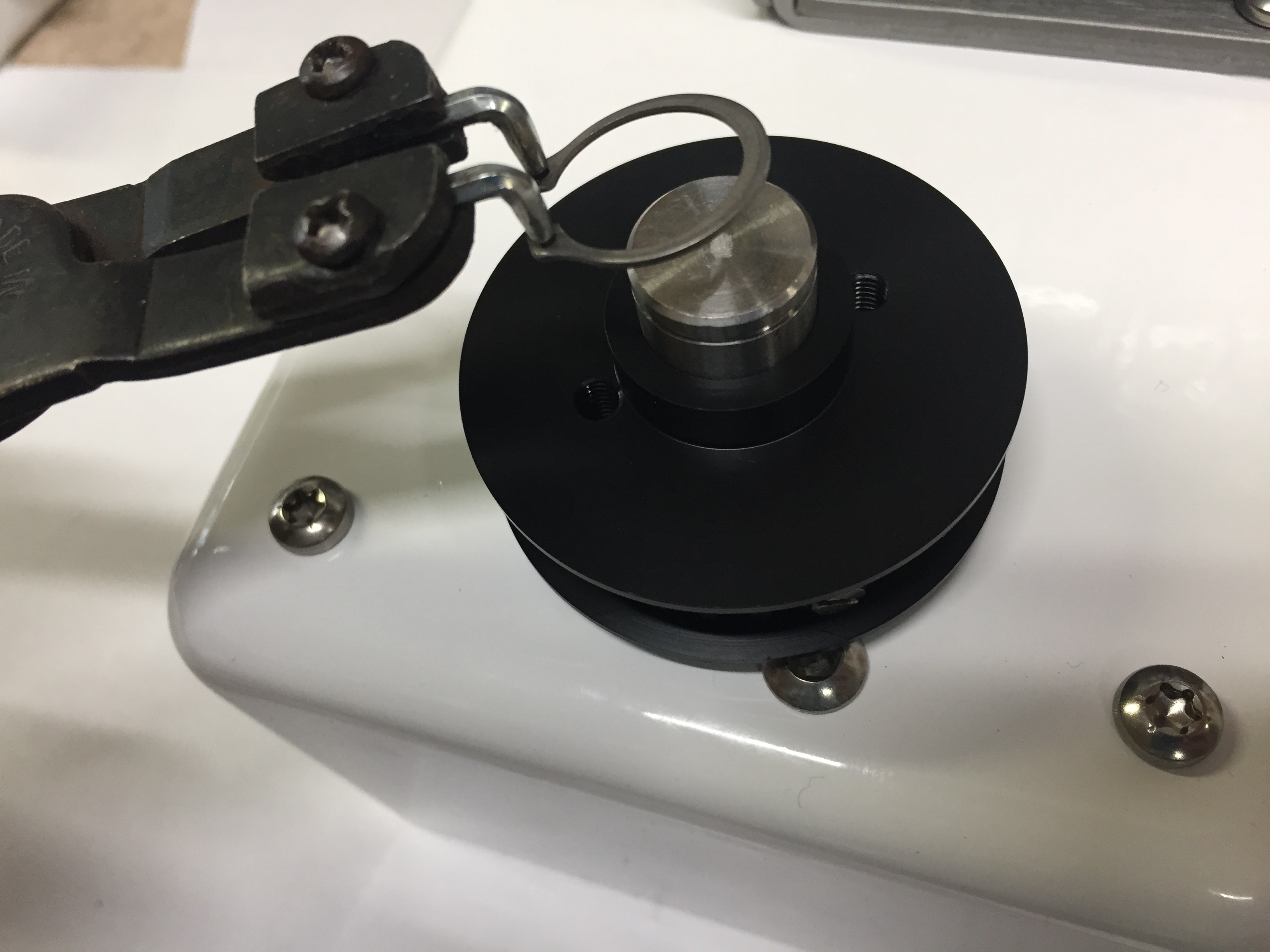
Remove the retaining ring, then remove the drive pulley gear from the drive shaft.
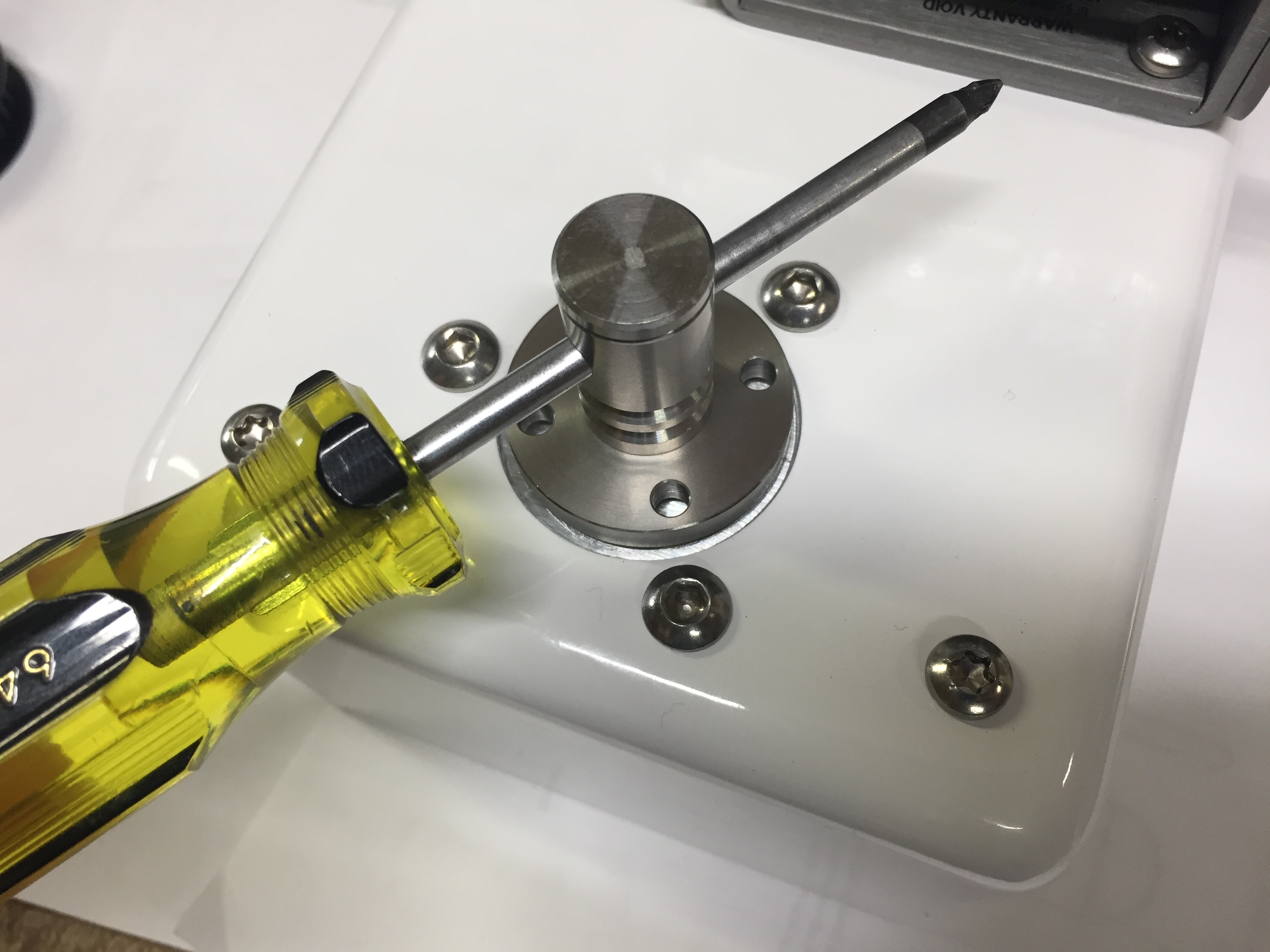
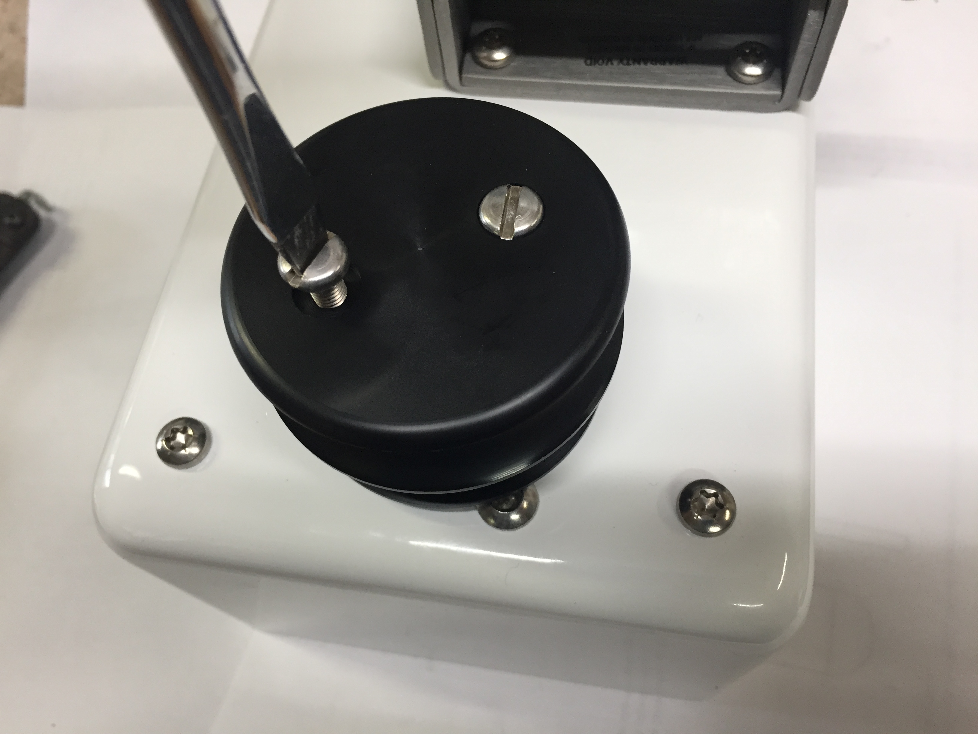
Remove the drive shaft. There is a hole in the shaft. To remove the drive shaft, insert a screw-driver (3⁄16” or 4.75mm diameter rod) and unscrew the stainless shaft from the motor shaft. It has normal threads—rotate the shaft counter-clockwise to loosen.
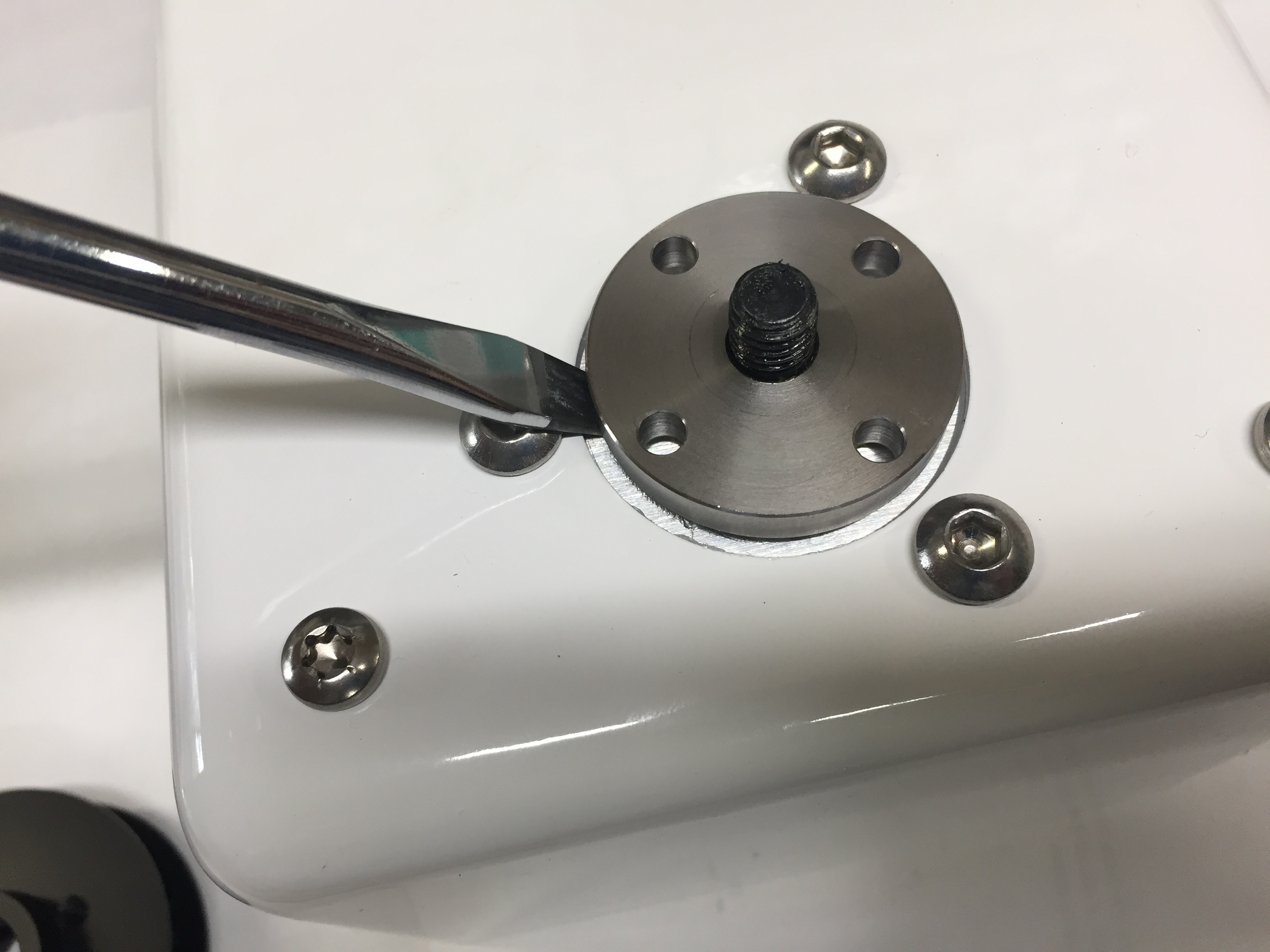
Gently pry the circular plate off the knurled motor shaft; gently pry all around the plate, force is not needed. Avoid prying against the aluminum box—use one of the bolt heads instead (as shown in photo). Do not remove or lose the black rubber O-ring found under the plate (size 110)—this is the watertight motor shaft seal.
Clean the drive plate, shaft, and hub of the drive pulley gear. Oil or grease the parts before reassembly. Be sure to work some oil into the detent ball that protrudes into the hole of the drive pulley gear.
Reassemble clutch. Adjust belt tension.
Note
There should be an even gap of about 1⁄16” (5mm) between the end of the shear pins and stainless steel drive plate. If one of the pins is too close to shaft-plate, it may tend to catch in the plate holes when the wheel is turned. If the pulley does not turn freely, the pins are not even, or the pins are too close to the shaft-plate, back off one or both of the screws slightly.
8.5. Connector Maintenance
Connectors for the power cable and control cable, if installed, should be maintained by applying dielectric grease to both plug and socket contacts each season. Caps should be in place and tight if plugs are not fitted together. Connectors are a liability if not maintained and kept greased. The cable jacket should be kept sealed and not open or exposed.
Warning
Do not use corrosion inhibitor, Boeshield T-9 or similar lubricants on electrical contacts. They can leave an insulating film which inhibits electrical connections and is difficult to remove.
Warning
No cables are detachable from their boxes. The black cable fittings on the control box and motor box are not plugs—do not loosen them. Attempting to remove them will void the warranty and may cause damage. The control box cable wires and power cable wires attach directly to circuit boards inside their respective box.
Note
An extension cable is available to easily extend the length of the control cable without cutting the cable. Do not cut or splice the control cable: the original factory control cable with its connectors is required for factory servicing if ever required.
8.6. Wheel Pulley
After a season or two, check to make sure the wheel pulley is still centered on the steering wheel and adjust if needed.
Warning
Do not over-tighten J-bolts or the pulley will warp and distort over time. Tighten each J-bolt until it makes contact and grips the spoke, then tighten the nut only another 1⁄4 turn.
8.7. Factory Service
It is recommended that the autopilot be returned for service to have the watertight seals replaced every 5 years depending on weather exposure and amount of use. This is also worthwhile if it has been used for many years and you are planning an extensive passage. There is a nominal charge, but if the seals become worn or brittle and salt water enters the unit, repairs may be extensive. The motor box and control box should be securely bubble-wrapped with 1⁄2” bubble-wrap, then separated by cardboard and boxed, and boxed again with 1” of peanuts when shipping.